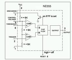
Ic 555 Internal Diagram
Ic 555 diagram block internal timer ic555 circuits integrated ne555 pinouts astable modes bistable monostable explored Ic 555 timer history lm555 internal cmos diagram invention story derivatives 555 timer draws zero off current
electronic hobby circuits: ne 555 ic internal diagram
Ic 555 pinouts, astable, monostable, bistable modes explored The history of 555 timer ic 555 timer ic diagram block working functional principle internal circuit schematic comparator avr pic ready help
How does ne555 timer circuit works
555 timer ic diagram block astable multivibrator circuit using internalAstable multivibrator using 555 timer 555 timer block circuitry simplified represents draws ne555Ne internal circuits hobby electronic ic diagram.
Ic 555 pinouts and working explainedReady to help: functional block diagram of ic 555 555 ne555 datasheet ic555 ci pinout integrado circuito monostable engineersgarage astable 5x bipolar modes555 ic lm555 timer ne555 diagram internal schematic block pinout ne556 modified fairchild pinouts working control pcb failure robot following.

555 timer ic: introduction, basics & working with different operating modes
Electronic hobby circuits: ne 555 ic internal diagramTimer 555 circuit diagram schematic ne555 datasheet pinout discrete kit does block circuits transistor works eleccircuit integrated connection functional pins .
.


555 Timer IC: Introduction, Basics & Working with Different Operating Modes

IC 555 Pinouts and Working Explained
electronic hobby circuits: ne 555 ic internal diagram

The History of 555 Timer IC - Story of Invention

555 timer draws zero off current
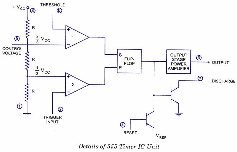
Ready to help: Functional Block Diagram of IC 555

IC 555 Pinouts, Astable, Monostable, Bistable Modes Explored
